Sure, Ziggee †

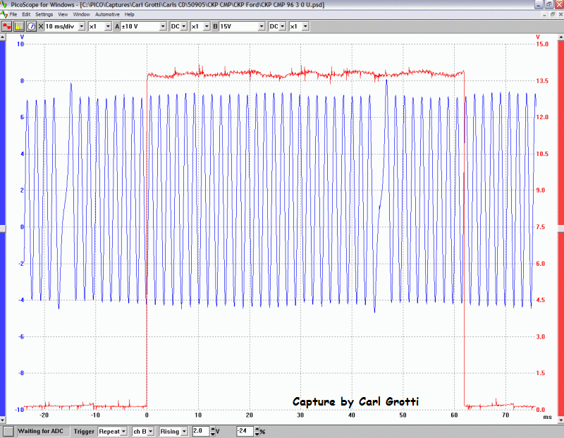
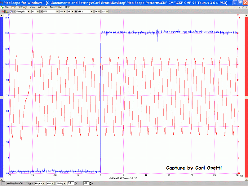
Here is how the CKP and CMP look:

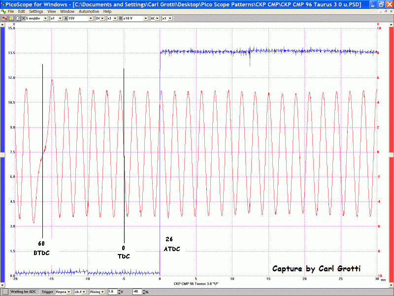
The crank signal is a 36 minus one tooth ring and the missing tooth is at 60 degrees BTDC, for a 6 cyl. †The sensor is a floating ground type VRS, so be sure to stab the correct wire so the signal is 'right side up'. †The signal should rise in the missing tooth region when you have it right. †The center of each tooth is 10 degrees. †The signal crosses zero going negative as the center of a tooth aligns. †Don't be concerned that the signal 'floats' a bit above ground. †This is normal because it's a floater and we have the scope referenced to vehicle ground.
The Cam signal is a hall effect 180 degree signal. †It's high for one crank rotation and low for the next.
We can set these up with the CMP rising or falling edge.

Here, we use the rising edge.

Here we have added the degree markings. †The rising edge of the cam signal should be at 26 ATDC #1 so 180 degrees of cam rotation later it will fall at 26 ATDC #5.
The cam sensor can be installed 180 degrees out and the signal will look perfect and the PCM will not know the difference but inject fuel at the wrong cylinder at the wrong time.
You can use compression #1 or #5 to set these up. Just be sure the CMP falls ATDC #5 and rises ATDC #1. I rough them in by hand then do the fine adjustment with the scope, engine running. In some applications, like the Windstar, rather than shedding blood to remove the #1 plug, I just use #5. Keeping in mind that the CMP vane should be leaving the sensor instead of entering it as it would be for #1 compression.
This procedure works for any EDIS 6 cyl with a hall effect cam sensor.

 Home
Home

 Help
Help

 Search

 Member Map

 Event Calendar

 Register

 Login
Login


 Pages: 1

